Retro & Vintage Computers and Appliances
Building an XTIDE ISA IDE Card for use with a Compact Flash Adaptor
Replacing an old, failed or missing hard disk in vintage and retro computers with a modern silent alternative
Rationale
One of the issues with old computers, especially those from the 1980s and 90s, is that not only are the hard disks likely to have failed or be failing, making excessive noise or have significant numbers of bad sectors, but they almost all use MFM and RLL interfaces incompatible with modern hard disks. Even in machines using IDE, which became common in the early 1990s, the computer BIOS very often will not recognise anything other than a very small selection of disk sizes which must have an exact match of disk geometry.A solution to this problem comes in the form of the XTIDE BIOS, an add-in boot ROM designed to work with almost all IBM PC compatibles from the first 8088 based IBM PC all the way to the last ISA machines built in the late 1990s. When added to a PC this additional BIOS runs when the system boots and will auto detect most IDE interfaces and disks, allowing them to boot. It also adds some additional abilities such as being able to boot a floppy disk image over a serial connection, which can be extremely useful for testing and configuring machines with faulty proprietary floppy drives that require special setup or boot disks.
But what if like most older machines, your PC does not have an IDE interface at all? This should be trivial to solve, even on the oldest PCs with only 8 bit slots. An IDE interface is really just a buffered extension of the ISA bus, so with just a few chips an IDE interface can be added, you just need a compatible boot ROM which XTIDE provides.
The XTIDE boot ROM adds another ability as well. Even if your machine has an IDE interface and configurable BIOS, mechanical disks are always a point of failure and even new IDE drives are becoming uncommon. Instead of a mechanical disk, you can use a Compact Flash card with a simple adaptor. Since Compact Flash cards use an IDE interface themselves, these can also, with an adaptor, be connected to an IDE port. However Compact Flash cards usually appear as hard disks with a very large number of heads to the system, so again the XTIDE BIOS can solve this issue if there are any compatibility issues.
What we need
So we have a solution to pretty much any hard disk problem on old PC compatibles, what exactly do we need? We could write the XTIDE boot ROM to an EPROM and put it in the boot ROM socket of an old ISA network card. This would give us modern IDE support on machines that have an IDE interface, as well as a network port. However, we'd still need to add an adaptor for compact flash cards and there's a risk of incompatibility with the built in IDE controller. That solution also requires a working ISA network card with a boot ROM socket, the network card to be configured correctly and a compatible programmed EPROM or EEPROM, which itself requires a programmer and potentially other equipment such as an EPROM eraser. Luckily there's a much easier way.The solution is to build an 8-bit ISA card with an IDE interface and EEPROM socket, which requires no separate programming as we can write the XTIDE BIOS to the EEPROM using the card itself. We could solder a compact flash slot directly to such a card, but soldering the fine pins required for the CF slot can be challenging. It’s much easier to buy a simple IDE to CF adaptor for around £ 4 and plug it directly into the card.
Choosing what to buy and build
We need an XTIDE card, a Compact Flash adaptor and a Compact Flash card. In order to easily fit in most PC cases, the IDE connector on the XTIDE card should really be at the rear edge of the card. Then we can plug a Compact Flash adaptor and card directly onto it and not block any other slots. As a bonus, some CF adaptors can be powered by pin 20 on the IDE interface, meaning no other power cables are required. We want to buy an adaptor of that type if possible.The first XTIDE card I built was made using a PCB bought via Ebay and labelled AAPRO which also came with a pre-programmed EEPROM. This card worked ok but I was unhappy with it. Not just because it had almost no documentation, did not match any of the well known open source designs, had a non-standard EEPROM that appeared impossible to update without a separate programmer and had a white solder mask that made the tracks hard to see and looked very out of place in a vintage machine, but because the IDE connecter was at the top of the card. This meant that plugging in an adaptor would always require some sort of extension or additional connector to avoid being obstructed by the case or blocking other slots. Since I could find absolutely no information about the AAPRO card online, not even a schematic or DIP switch settings, I've written a brief review and will provide more info such as configuration details on a dedicated page for anyone who needs it.
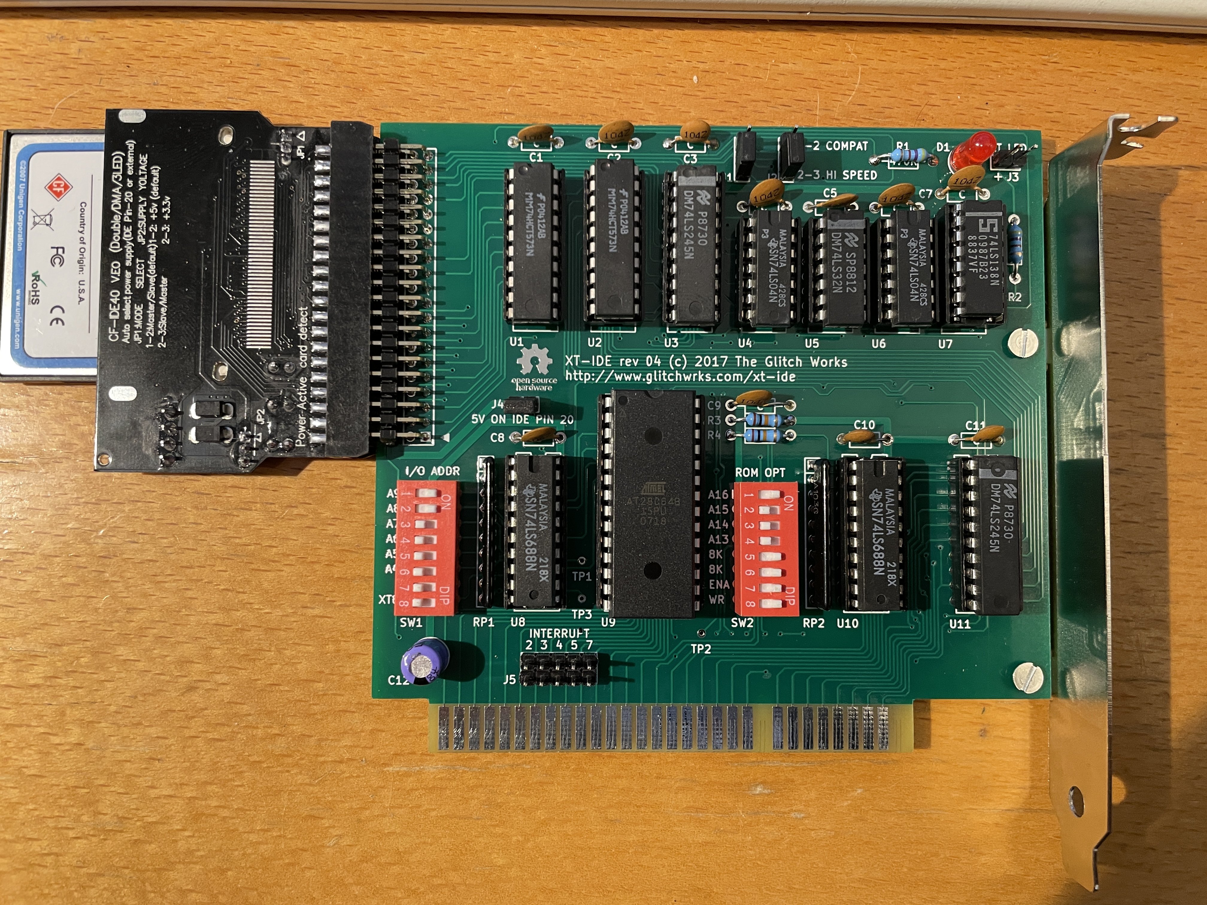
The hunt was on for a card that met those requirements and it didn't take long to find the perfect one. The Glitch Works XT-IDE revison 4 is published as an open-source design and is fully documented with even the PCB Gerber files provided, so it’s easy get them made by any PCB manufacturing company, or potentially even etch your own.
Obtaining the parts
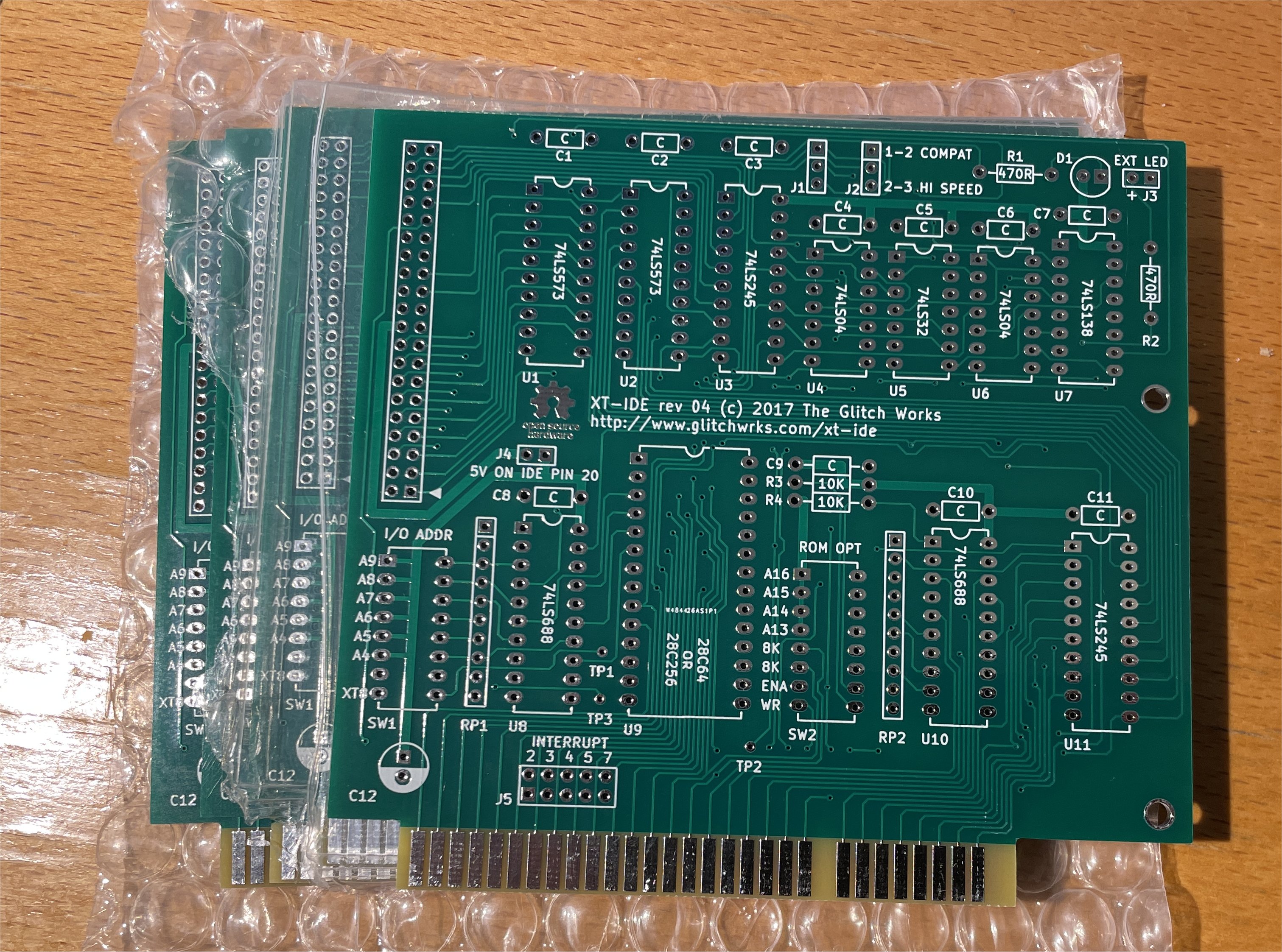
The first thing needed was the PCB. I had originally intended to buy a board from The Glitch Works directly, but they're in the US and with shipping costs a single bare board worked out about US$ 40 not including any import duties, costs or VAT. I also looked on Ebay but at that time there were none available in the UK and only a few in the EU at a similar price to the US board. I therefore decided to get the board made by PCBway in China as their minimum order of 5 boards only cost around US$ 50 including shipping and I knew I would need more than one.Looking online I found photos of several different versions of the "revision 4" Glitch Works PCB. The one on Githib was labelled "2017" but I also saw photos of what appeared to be a later "2019" board. I decided to go with the 2017 version on Github as that seemed the best documented. Another decision was if the edge connector should be gold plated. Gold plating almost doubled the price and looking at my collection of original ISA cards, many weren't gold plated back in the day and the ones that were seem to have slightly more obvious tarnish or corrosion than those that didn't. There's some debate about this online, but the edge connectors on many early 80s computers such as the Sinclair range weren’t gold plated and it's very rare for the connectors not to work fine after 40 years, so it appears to be an unnecessary extra expense. I did try and load the PCB design into KiCad before ordering, but it was created on a slightly earlier version and some errors were shown. However, in the PCBway web interface the board looked fine so I took a chance and placed the order. Just over two weeks later the PCBs arrived and were absolutely perfect.
The exact Gerber file I used for the PCB order can be downloaded here.
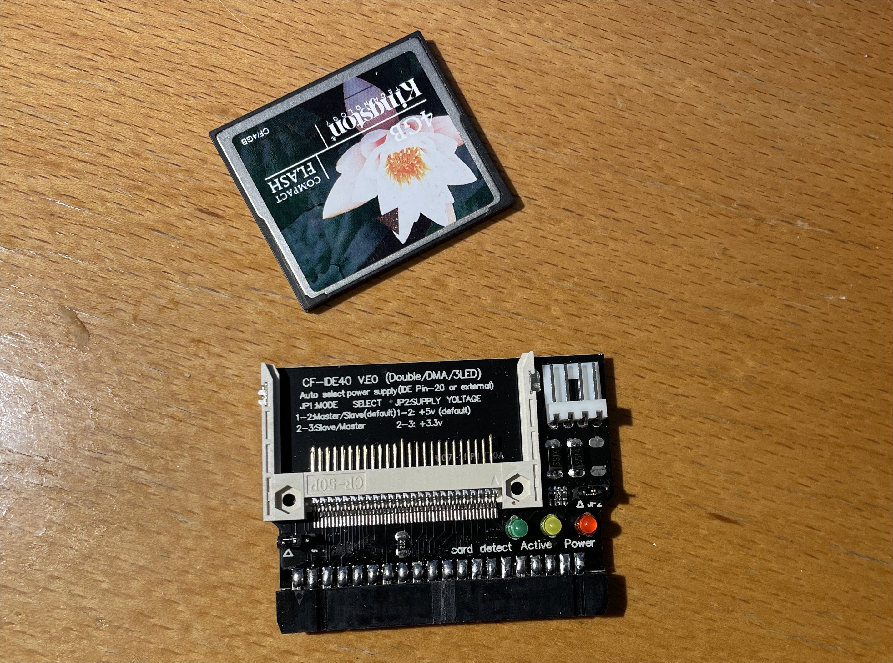
The next items are an IDE to Compact Flash adaptor and Compact Flash card. Looking online it seems some compact flash adaptors require external power and others can be powered via 5V on pin 20 of the IDE connector. Be very careful if testing or using this method, as getting it wrong will short the 5V rail to ground potentially damaging the computer's power supply. More on that later, but the CF adaptor I used looks like the one in this photo. I bought two of these from the same seller. Both worked fine, but for the first one I had to work out that the manufacturer had fitted the 40 pin connector the wrong way around! After removing the plastic notch so it would fit the other way on a motherboard IDE port, I confirmed it worked. For the second which was bought a week later, the seller had already seemingly cut off the notch by hand just as I had. I guess they only realised when someone (not me) complained! :-)
For the Compact Flash card, I used whatever old cards I had lying around. I wouldn't use too large a card as for DOS 6.22 the maximum partition size is 2GB and for older versions 32 MB. It's probably best to find something that's similar in size to the disk originally sold with the machine.
You'll need a reasonable quality temperature controlled soldering iron, solder, de-solder braid, side cutters and experience soldering ESD sensitive components with an anti-static strap and the knowledge how to safely use them, to build this board. This website can't teach you these skills or how to solder, but Big Clive on Youtube has a video on buying cheap but reasonable soldering irons.
You'll also need the chips and components to build the board. A component list can be downloaded here. Note that it should be possible to substitute LS, ALS, ACT, or HCT equivalents for the 74 series chips, but not any other variations. Make sure you order chips with DIL pins, not surface mount ones. Also, I had a lot of trouble with the first 28C64B EEPROM (it would sometimes error when programming, or the machine would boot and then sometimes randomly hang) and after reading about a lot of fakes online I've come to the conclusion the one I bought was a fake. I replaced it with a 28C256 and have had no issues. I therefore would recommend you use a 28C256 rather than a 28C64B and doing so will also give you more options as to which version you run, as only some versions will fit on the 28C64B. I also recommend you fit sockets for all ICs, not just the EEPROM, to assist with any issues.
You don't need to buy a bracket for the card, but if you use it without one make very sure it's carefully fitted in the ISA slot the correct way round and does not come loose. Adrien of Adrien's Digital Basement has already damaged one card by fitting it without a bracket the wrong way around as it will short out the board.
Construction
Solder the 11 decoupling capacitors first, followed by the resistors, resistor packs, IC sockets and DIL headers and switches.Things to note: Make sure to fit the DIL switches the right way around. Look at the numbers and make sure they match same order as in the photos of the completed board.
Make sure to use a right angled IDE header so the SD card adaptor can be fitted inline behind the card. You may need to stand the header a little off from the board to ensure the adaptor's connector edge does not foul on the edge of the PCB. Ensure the adaptor fits fully onto the IDE header pins before soldering the header in place. Make sure the resistor packs, 100uF capacitor, LED and IC sockets (which have a small notch at one end) are fitted the correct way around. The 11 decoupling capacitors are not polarised so can be fitted either way round. Put a jumper on each of the top two jumper pins in the top "compatible" setting but do not put any jumper on the "5V on IDE pin 20" jumper. Note that the IRQ jumpers are not currently used and should not have any jumpers fitted. Do not connect the CF card adaptor at this stage.
Once soldered do not fit the chips. Clean the flux off the board using Isopropyl Alcohol and very carefully visually inspect the board for poor, missing or shorted solder joints. Using a multimeter check for shorts between VCC and GND on each IC socket. Once you're absolutely sure it appears ok, go and have a cup of tea and then come back and check again in case you missed something. When absolutely sure, insert the board in the computer making sure it's the correct way round and without the chips or CF adaptor installed. Power on the PC and check it still boots. Be aware there is a risk you may damage your computer or power supply due to poor soldering. If it powers on ok, switch off and unplug everything, remove the board and using suitable ESD protection, install the chips. Set the DIP switches as follows and reinstall the board back in the computer but do not connect the CF card adaptor.
Typical settings are a card address of D000 and port of 300. These might need changing to avoid conflicts in some machines but are a good starting point. DIP switches for address D000 are: A16=1, A15=0. A14=0, A13=0. Set the two "ROM Type 8K" switches to 0 for 28C256 and 1 for 28C64B. Set ENA=1 and WR=1. For port 300 set: A9=1, A8=1, A7=0, A6=0, A5=0, A4=0, NA=0, XT8=0.
Note the XT8 switch is to enable "slot 8" compatibility on the original IBM XT. Enabling this requires an extra circuit board and is only required for special slot number 8 on the original IBM XT. I understand you can still use it in any other slot on an original IBM XT with this switch off and it will work just as it would in other machines. If you're not using an original IBM PC XT with only slot 8 empty, you probably don't need slot 8 compatibility.
Programming the EEPROM
Programming the XTIDE BIOS into the board's EEPROM is trivial using the board itself. In fact this is really the only way to do it as you need to choose your configuration options at the same time. You will need a floppy disk, or another working hard disk, which is bootable to DOS and which has the XTIDE bin files and xtidecfg.com program on it. You may be able to use a "null modem" serial cable to copy these from a newer machine with a serial port to the old machine, as long as it boots, using Laplink which itself can be installed over a serial connection. I used XTIDE version r613 from www.xtideuniversalbios.org/binaries/_older-versions/r613/ which can also be downloaded as a ZIP file here.Boot the computer with the card installed and run xtidecfg.com.
You will need to choose a version to flash. I recommend IDE_XT.BIN as this should work with just about any machine or processor. Other versions may be slightly faster on newer processors, but IDE_XT.BIN seems to be the most compatible. Note that I may be mistaken and there may well be machines that only work with other versions, but I've not yet found one.
To clarify the filename labelling, IDE_XT.BIN is for Intel 8088 and 8086 CPUs and seems to work well with almost anything. IDE_XTP.BIN is optimised for NEC V20, V30, and Intel 80286 CPUs. There are also versions for 386 processors and smaller versions that miss some features if you only have the smaller 28C64B EEPROM.
Set the configuration options in xtidecfg.com. Some good defaults are: Block Mode Transfers=Yes, CHS Translation=Auto, Internal Write Cache=Auto, EEPROM type=28256 (unless using a 28C64). Select "16 bit in 8 bit slot" or "XTIDE rev2 or modded rev1" as the board type. Base address=300, Control block=308, Full Operating Mode=Yes.
Select the option to write the EEPROM.
Once complete allow the machine to reboot. You should now see the XTIDE boot message and after a delay the machine will try to boot as before from floppy or another disk.
If you have any issues flashing the chip that causes the machine to hang on reboot, you can power on the machine with the card fitted and the "Enable" DIP switch off to disable the ROM at boot. Then once the machine has booted and you’re ready to try flashing the chip again, turn the switch on before flashing.
Installing the Compact Flash adaptor and card
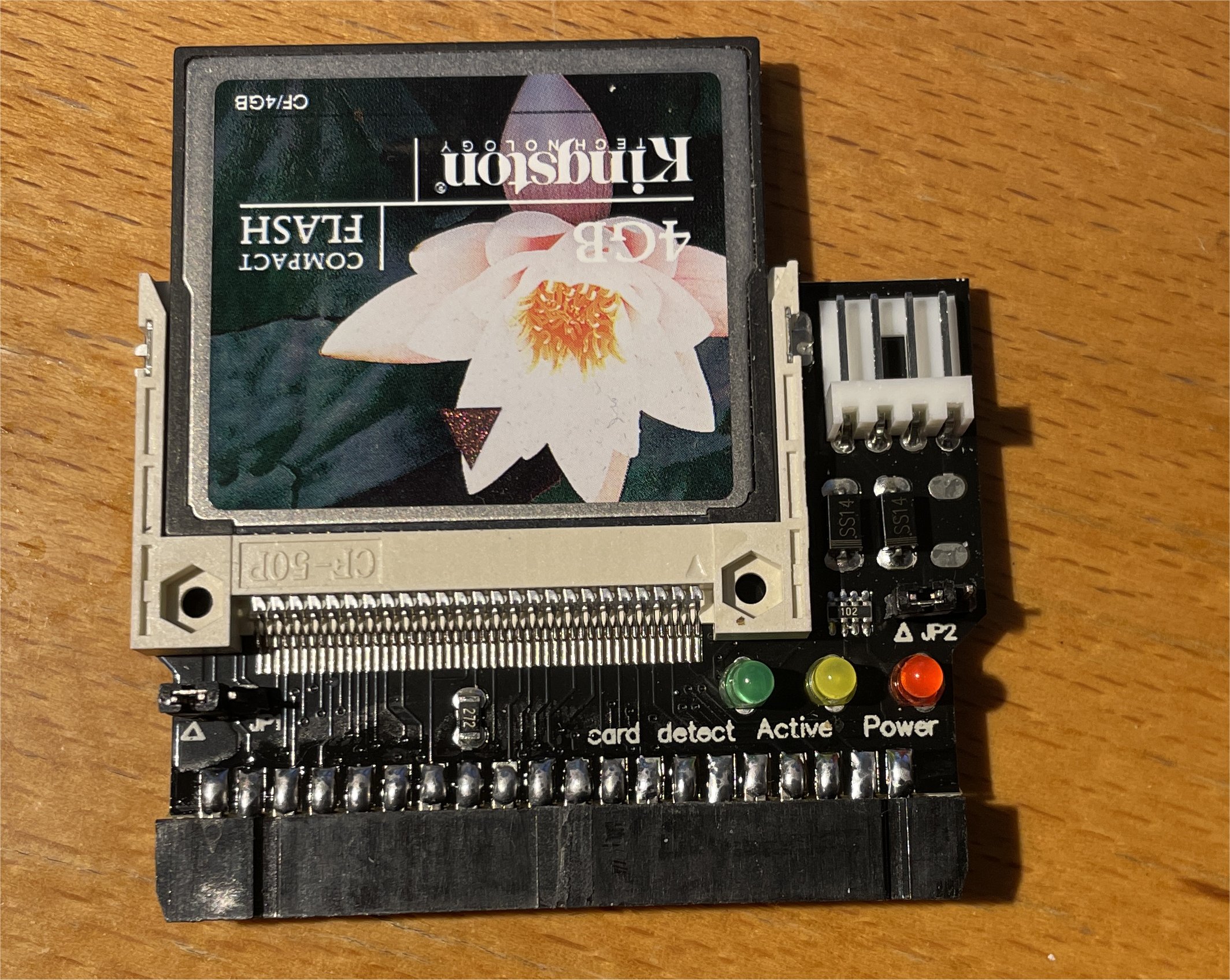
When plugging the CF adaptor into the board make sure it's plugged in the right way around. Pin 1 is marked by a triangle on the XTIDE PCB and on the adaptor shown, the CF card faces away from the component side as shown in the photos. If using an IDE connector with a notch, I believe it would normally face towards the component side of the board but be aware as mentioned earlier, in the two examples I bought the connector fitted the wrong way around and therefore so was the notch.Some adaptors can take 5V power on pin 20 of the IDE connector but others will only work with a separate power connecter (for example a floppy drive power cable) connected to them. However, it's worse than that, as the ones that don't support pin 20 power will often short this pin to ground, potentially damaging or destroying the computer or its power supply. It's therefore vital to check and be sure the adaptor supports this before installing the jumper to enable it.
The adaptor I used in the photo supported this, but even if you have an identical looking adaptor, don't assume it will. If you're unsure, connect a separate power connector and do not install the jumper. However, if you are going to try and use pin 20 power, with the XTIDE card removed from the computer but the SD card and adaptor connected to it, you should check with a multimeter for a short between either two pins of the "5V on IDE pin 20" and ground. Try with your multimeter probes reversed as well, just in case the adaptor card has a diode inline. If you're absolutely sure it's safe to do so, put a jumper across the "5V on IDE pin 20" pins and ensure no other power cable is connected to the Compact Flash adaptor.
With the EEPROM programmed and a correctly configured Compact Flash card installed, the system should detect and list the CF card on the boot screen. You can then boot from a floppy and install DOS on the Compact Flash card as you would for most hard disks. I'd recommend using at least DOS 6.22 for this process. It's also possible to use a CF to USB adaptor to copy files to and from the CF card via a modern PC, though be aware this can cause file corruption and issues with some DOS versions, systems and cards.
Once it's all working you can optionally connect the computer's original hard disk activity LED to the card. Please check and meter the connectors carefully and confirm voltage and polarity compatibility before doing so.