Raspberry Pi Based STL Receiver and Backup Audio Source
NOTE:
This device was created in 2014 and these notes are now out of date and incomplete but have been left here for historical reference.
We've now moved to using dedicated PCs with 192 KHz sound cards running software such as Stereotool to generate the entire FM multiplex.
This page documents how we built a rack mounted transmitter site STL solution. This is a fully featured device designed as a direct replacement for the typical "Barix" boxes used by many stations, but with a far greater range of features and capabilities all managed from a simple web interface. The system also includes an API to enable integration with our remote studio switching platform, the capability to control an RDS encoder to update, for example, RadioText and Traffic flags, monitoring and control functions as well as automatic fall-over to an emergency source or recording should the data link fail. Based on open-source software you're able to easily customise and modify the system to fit your exact requirements.
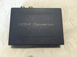
The key component in the STL is a Raspberry Pi board. The Raspberry Pi has, quite frankly, terrible audio on-board. However it is able to output perfect lossless digital audio to an HDMI connected TV which can also be converted back to superb quality analogue. Modern transmitters and processors typically have balanced stereo analogue inputs and often (certainly in the case of Broadcast Warehouse DSPX processors and their newer V2 transmitter range) an EBU compatible digital input which can be used for a completely flawless connection. So how do we create a perfect digital output or very high quality analogue output? The Raspberry Pi has lots of options, almost all of which are far from ideal. Its USB interface suffers from timing and reliability issues due to the way its wired internally and although there is a large third-party industry of add-on boards, these can be expensive or complicated to configure. So how do we get high quality digital and analogue audio out, cheaply and simply? Easy, we buy a cheap HDMI to analogue/SPDIF breakout box from Ebay (approx £12)! Despite all the available specialist add-on boards, nothing seems to match the quality, simplicity and reliability (and that's not even taking in to account the low price) of just connecting to the HDMI output with a simple breakout box containing its own decoder chips and D/A converter! All it takes are a few extra lines in the Pi's config.txt file to activate the HDMI without a screen, and the hardware is almost complete!
The parts we'll need are:
A Raspberry Pi Model B 512MB version or better - Approx £30
A 4GB or larger SD card (use high quality/speed) - Approx £3 (we had one spare)
An HDMI audio (analogue/digital) breakout box - About £12 (Ebay)
A short HDMI cable (as short as possible) - About £1.50
A 5V PSU with minimum 2 amps output - About £10 (but we used one from a Cisco 801 router)
A 1U rack mount case - About £30 (but we re-used a case from a broken audio breakout box)
Total: £86.50 Approx (in our example £43.50)
Note that a high quality power supply is essential. Don't use a cheap wall plug or mobile phone charger, even if it's rated at 2 amps.
These instructions refer directly to the Cisco power supply we used, though this will be simpler if a standard "off the shelf" PSU is used:
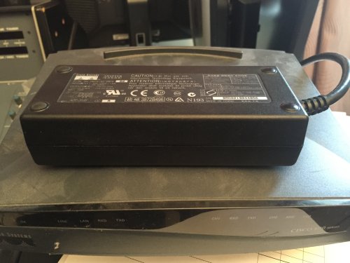
The power supply we used was from an old Cisco 801 ISDN router. Nobody uses ISDN for networking anymore and we would have been lucky to sell this for 99p on Ebay.
Opening the Cisco PSU (part number 34-0875-01 which claims to provide up to 3A on it's 5v rail, in case you're interested) we see it's well made and they've even kindly marked the voltage output connections on the PCB:
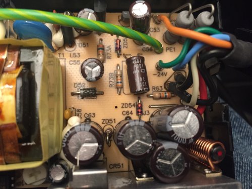
Cisco Connections:
+5v - Red
ROF - White (Remote on/off. Connect to a black GND wire to make the PSU work!)
-24v - Green
GND - Black (x2)
GND - Blue (Unused)
-71v - Orange
What on earth Cisco use a -71v line for in a simple router boggles the mind, however for safety I cut and removed the orange and green (-71v and -24v) connections inside the PSU case as +5v is all we need. I also trimmed back the ground braid at the remote end of the cable and only used the black ground wires. Remember, if you trim back the cable on this type of PSU you MUST insulate any unused wires if you've not already disconnected them elsewhere. It turns out this type of PSU requires a ROF (remote on/off) connection before it will work! This caused me a few mins of head scratching and tracing of the circuit before I realised the white ROF cable must be connected to one of the black ground wires to enable power to be produced!
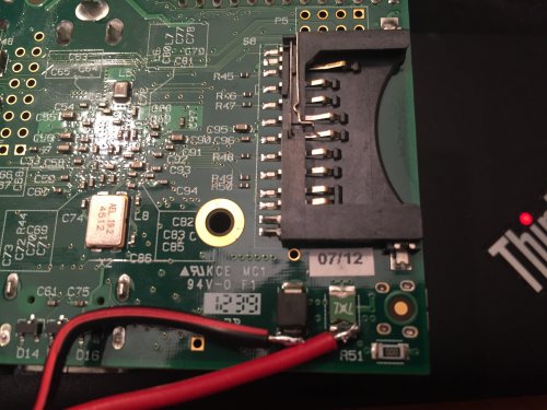
Once we've identified the 5v and GND connections and soldered the ROF line in place (for the Cisco PSU) we can then make a loom to connect the Raspberry Pi and HDMI adaptor. I've soldered my power cables directly to the Raspberry Pi for greater reliability, however there is a high chance you might ruin your Raspberry Pi so if you're at all unsure, use a USB cable. I also connected a green LED and 1K resistor across the 5v rail to indicate power.
Make sure your HDMI breakout box is set to "pass-through" mode for the audio if it has this option.
For status indicators, I've connected green and a red LEDs to GPIO pins 17 and 18, each via 1K resistors. The two LEDs share a common ground connection meaning just three wires need to be connected to the GPIO bus.
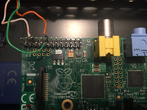
The LED labelling is as follows:
GPIO 17 - Green - "Run"
GPIO 18 - Red - "Fail"
Both LEDs will be off with any standard Raspberry Pi SD image, however our scripts will switch them as required. To test, you can turn them on manually at the Raspbian command line as follows:
That completes the initial hardware build.
To download the software, setup instructions and custom scripts click below:
Download STLTX1 V1.12
Screenshot of web interface:
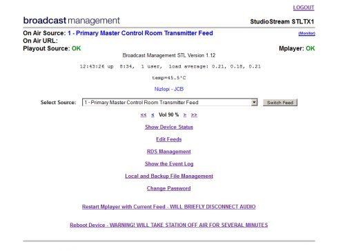
Please note that the software is still in development and some features (such as RDS control) are not yet released. I'm afraid I can't offer any support for devices built by other people.
Still to be documented:
Fibre to coax/EBU converter.
Hardware install of optional cooling fan.
USB extension cable added for RDS encoder connection.
NOTE:
This device was created in 2014 and these notes are now out of date and incomplete but have been left here for historical reference.
We've now moved to using dedicated PCs with 192 KHz sound cards running software such as Stereotool to generate the entire FM multiplex.
This page documents how we built a rack mounted transmitter site STL solution. This is a fully featured device designed as a direct replacement for the typical "Barix" boxes used by many stations, but with a far greater range of features and capabilities all managed from a simple web interface. The system also includes an API to enable integration with our remote studio switching platform, the capability to control an RDS encoder to update, for example, RadioText and Traffic flags, monitoring and control functions as well as automatic fall-over to an emergency source or recording should the data link fail. Based on open-source software you're able to easily customise and modify the system to fit your exact requirements.
The key component in the STL is a Raspberry Pi board. The Raspberry Pi has, quite frankly, terrible audio on-board. However it is able to output perfect lossless digital audio to an HDMI connected TV which can also be converted back to superb quality analogue. Modern transmitters and processors typically have balanced stereo analogue inputs and often (certainly in the case of Broadcast Warehouse DSPX processors and their newer V2 transmitter range) an EBU compatible digital input which can be used for a completely flawless connection. So how do we create a perfect digital output or very high quality analogue output? The Raspberry Pi has lots of options, almost all of which are far from ideal. Its USB interface suffers from timing and reliability issues due to the way its wired internally and although there is a large third-party industry of add-on boards, these can be expensive or complicated to configure. So how do we get high quality digital and analogue audio out, cheaply and simply? Easy, we buy a cheap HDMI to analogue/SPDIF breakout box from Ebay (approx £12)! Despite all the available specialist add-on boards, nothing seems to match the quality, simplicity and reliability (and that's not even taking in to account the low price) of just connecting to the HDMI output with a simple breakout box containing its own decoder chips and D/A converter! All it takes are a few extra lines in the Pi's config.txt file to activate the HDMI without a screen, and the hardware is almost complete!
The parts we'll need are:
A Raspberry Pi Model B 512MB version or better - Approx £30
A 4GB or larger SD card (use high quality/speed) - Approx £3 (we had one spare)
An HDMI audio (analogue/digital) breakout box - About £12 (Ebay)
A short HDMI cable (as short as possible) - About £1.50
A 5V PSU with minimum 2 amps output - About £10 (but we used one from a Cisco 801 router)
A 1U rack mount case - About £30 (but we re-used a case from a broken audio breakout box)
Total: £86.50 Approx (in our example £43.50)
Note that a high quality power supply is essential. Don't use a cheap wall plug or mobile phone charger, even if it's rated at 2 amps.
These instructions refer directly to the Cisco power supply we used, though this will be simpler if a standard "off the shelf" PSU is used:
The power supply we used was from an old Cisco 801 ISDN router. Nobody uses ISDN for networking anymore and we would have been lucky to sell this for 99p on Ebay.
Opening the Cisco PSU (part number 34-0875-01 which claims to provide up to 3A on it's 5v rail, in case you're interested) we see it's well made and they've even kindly marked the voltage output connections on the PCB:
Cisco Connections:
+5v - Red
ROF - White (Remote on/off. Connect to a black GND wire to make the PSU work!)
-24v - Green
GND - Black (x2)
GND - Blue (Unused)
-71v - Orange
What on earth Cisco use a -71v line for in a simple router boggles the mind, however for safety I cut and removed the orange and green (-71v and -24v) connections inside the PSU case as +5v is all we need. I also trimmed back the ground braid at the remote end of the cable and only used the black ground wires. Remember, if you trim back the cable on this type of PSU you MUST insulate any unused wires if you've not already disconnected them elsewhere. It turns out this type of PSU requires a ROF (remote on/off) connection before it will work! This caused me a few mins of head scratching and tracing of the circuit before I realised the white ROF cable must be connected to one of the black ground wires to enable power to be produced!
Once we've identified the 5v and GND connections and soldered the ROF line in place (for the Cisco PSU) we can then make a loom to connect the Raspberry Pi and HDMI adaptor. I've soldered my power cables directly to the Raspberry Pi for greater reliability, however there is a high chance you might ruin your Raspberry Pi so if you're at all unsure, use a USB cable. I also connected a green LED and 1K resistor across the 5v rail to indicate power.
Make sure your HDMI breakout box is set to "pass-through" mode for the audio if it has this option.
For status indicators, I've connected green and a red LEDs to GPIO pins 17 and 18, each via 1K resistors. The two LEDs share a common ground connection meaning just three wires need to be connected to the GPIO bus.
The LED labelling is as follows:
GPIO 17 - Green - "Run"
GPIO 18 - Red - "Fail"
Both LEDs will be off with any standard Raspberry Pi SD image, however our scripts will switch them as required. To test, you can turn them on manually at the Raspbian command line as follows:
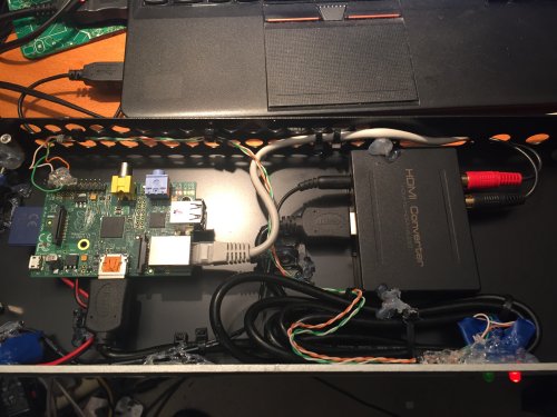
echo "17" > /sys/class/gpio/export
echo "out" > /sys/class/gpio/gpio17/direction
echo "1" > /sys/class/gpio/gpio17/value

echo "18" > /sys/class/gpio/export
echo "out" > /sys/class/gpio/gpio18/direction
echo "1" > /sys/class/gpio/gpio18/value
The Raspberry Pi was fixed to the case with a combination of the boxes existing mounts and adhesive PCB stand-offs. The power cable, audio cables and a short ethernet patch cable were secured and run through the back of the case for easy external connections. Cable ties and adhesive fastners were used to secure the various cables and the HDMI converter was glued in place using a hot glue gun. I could have spent a little extra money on chassis mount connectors, however in this application they would have served no purpose and might even have reduced reliability. In my trademark style I put a bit of hot glue on the connections, mounts, LEDs and anything else that looked like it could come loose. While it may look a little messy, it makes the final device tough and very resistent to knocks.
That completes the initial hardware build.
To download the software, setup instructions and custom scripts click below:
Download STLTX1 V1.12
Screenshot of web interface:
Please note that the software is still in development and some features (such as RDS control) are not yet released. I'm afraid I can't offer any support for devices built by other people.
Still to be documented:
Fibre to coax/EBU converter.
Hardware install of optional cooling fan.
USB extension cable added for RDS encoder connection.