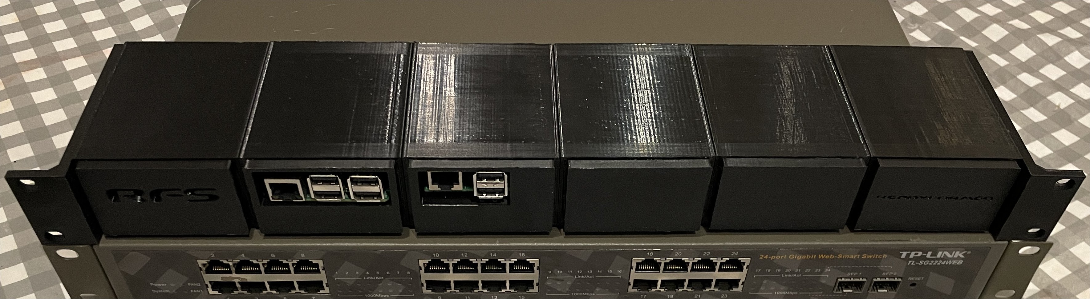
1U Rack frame with six trays for Raspberry Pi and similar devices
Page created: 09/12/2023.
DOWNLOAD FILES AS ZIP
This is a remix of an existing excellent 1U design by russross with changes to allow assembly using more commonly available M4 screws, elements added to more easily allow new types of tray to be created for alternative devices and for a Pi to be mounted in the opposite direction. In addition to technical and cosmetic changes, a top cover has been added to the frame and a lower cover to the trays to protect devices from other equipment.
In this design the front panel of each tray has a flat surface and forms the majority of the visible area. By printing the trays face down on the printer, this creates a very clean visual appearance which can be improved further by using a textured bed.
These frames are sometimes referred to as "hot swapable" but they're better described as "interchangeable". While you can easily remove a device without affecting the others, in some cases you may want to create an "appliance" of multiple devices, possibly with internal wiring. In that instance having panels that fit flush with the slot also becomes an additional consideration.
Trays are included for later Raspberry Pi models in both forward and reverse orientation, as well blanking panels and a tray for the original Pi from 2012.
Changes to the holder frame
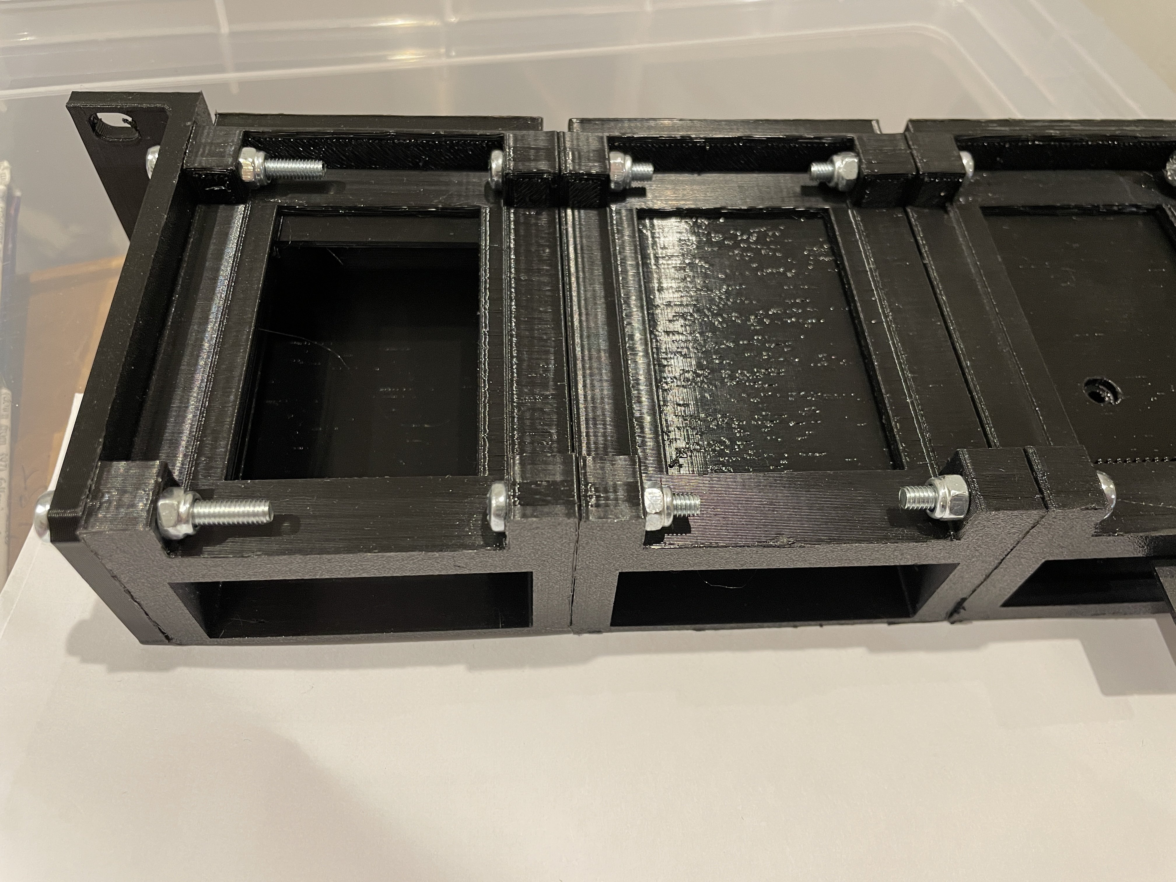
Instead of threaded rods, gaps have been added so screws and nuts can be used instead as these are often more easily available.
The connecting holes have been changed to accommodate standard M4 screws, as the original American size is hard to obtain in the UK.
The connecting holes have been lowered by 2mm and moved by 1mm towards the rear to allow the screw heads and nuts to fit.
The rear opening is now larger to make it easier to design modules for other devices or for a tray with the Pi reversed.
The slot for the Pi headphone socket has been made taller and deeper to allow other boards with different side ports to be used.
This slot is now also replicated on the right to allow a tray for a Pi mounted in reverse or alternative boards to be used.
The front angle at the base has been removed and a cover added to hide the area where the screws are now located.
A cover has been added over the top to help prevent adjacent equipment or cables causing damage or short circuits.
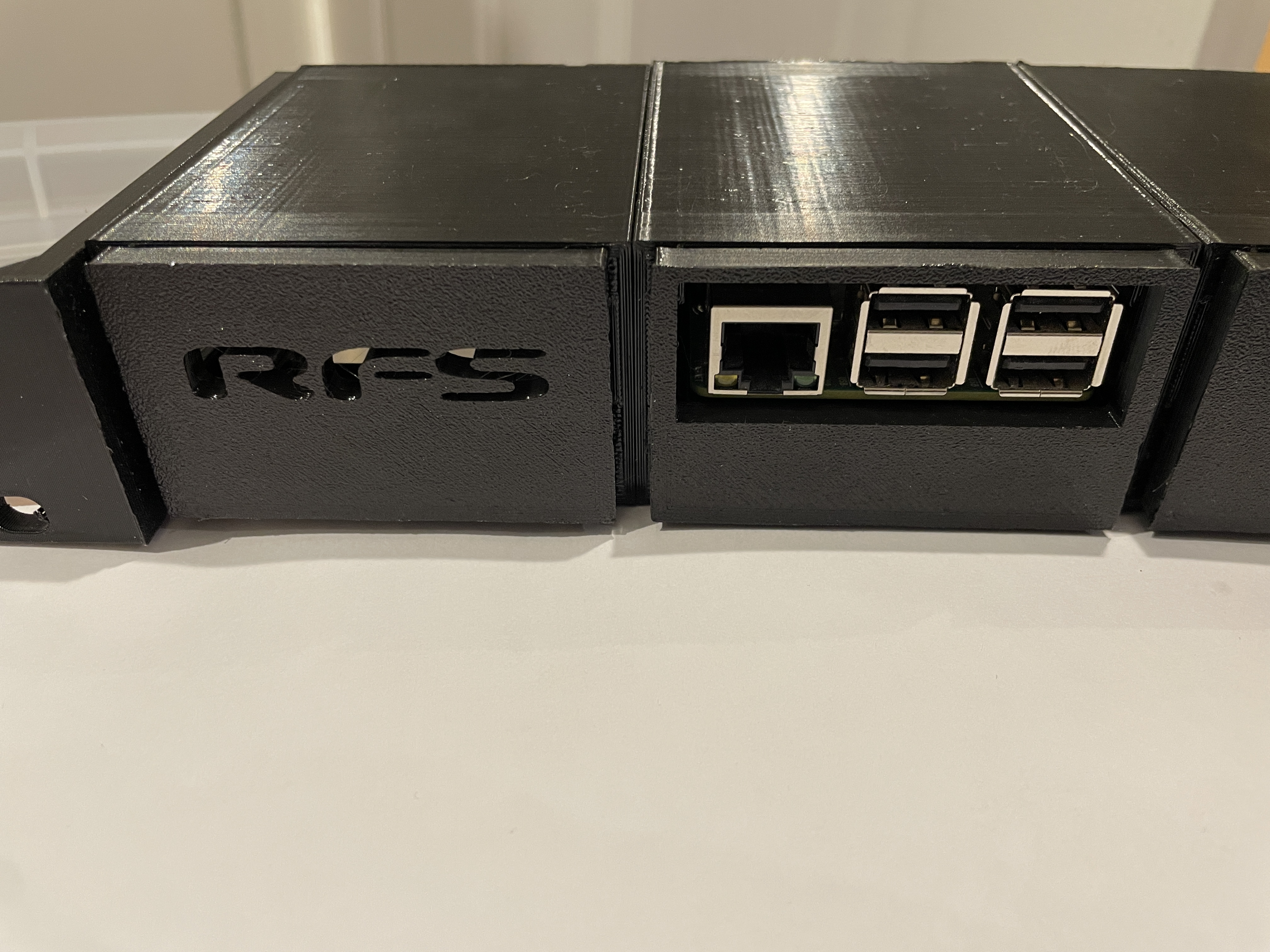
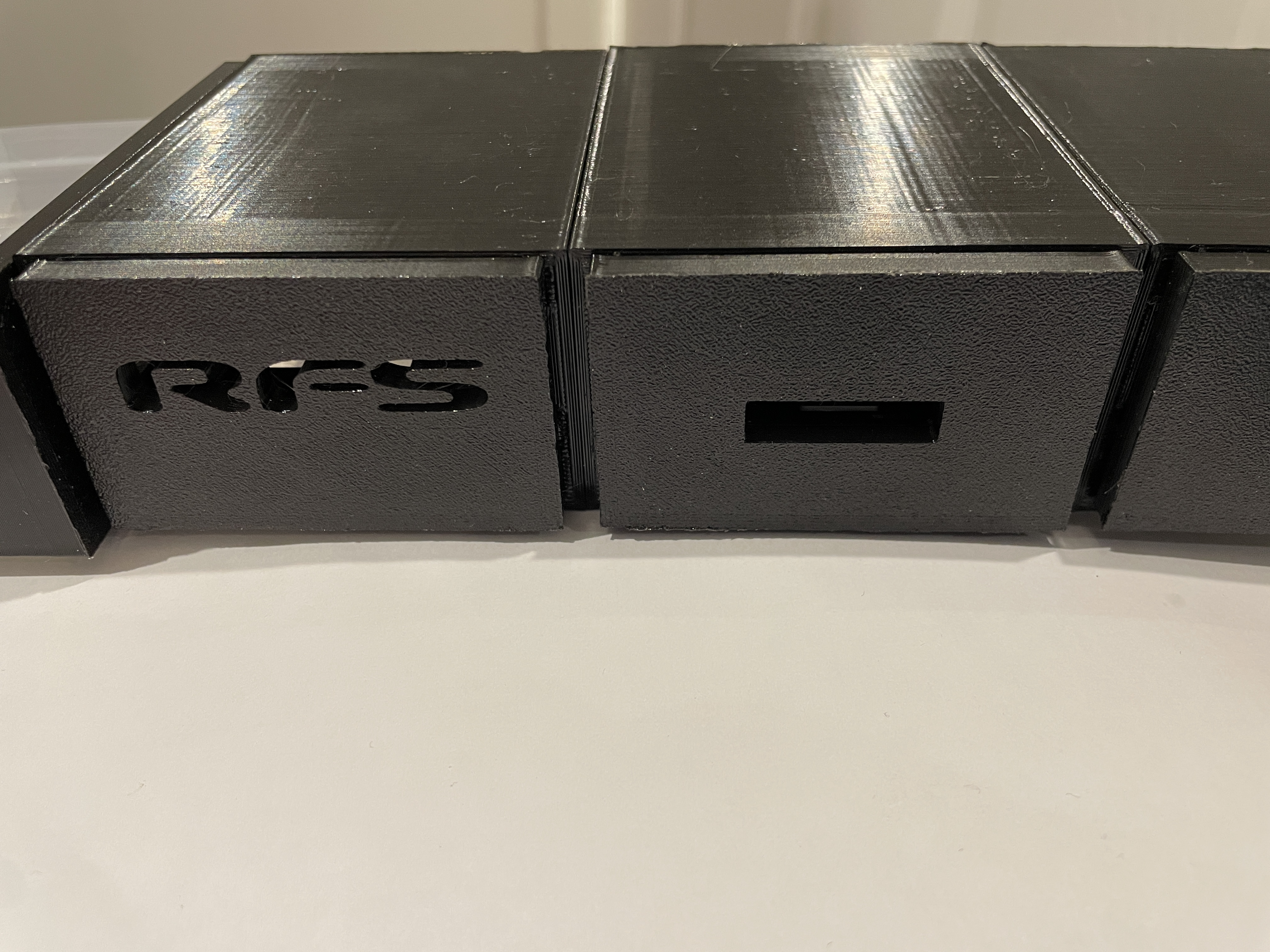
Readyformed text added to allow easy identification of the wider slot type. This text is hidden when a tray or blank is inserted.
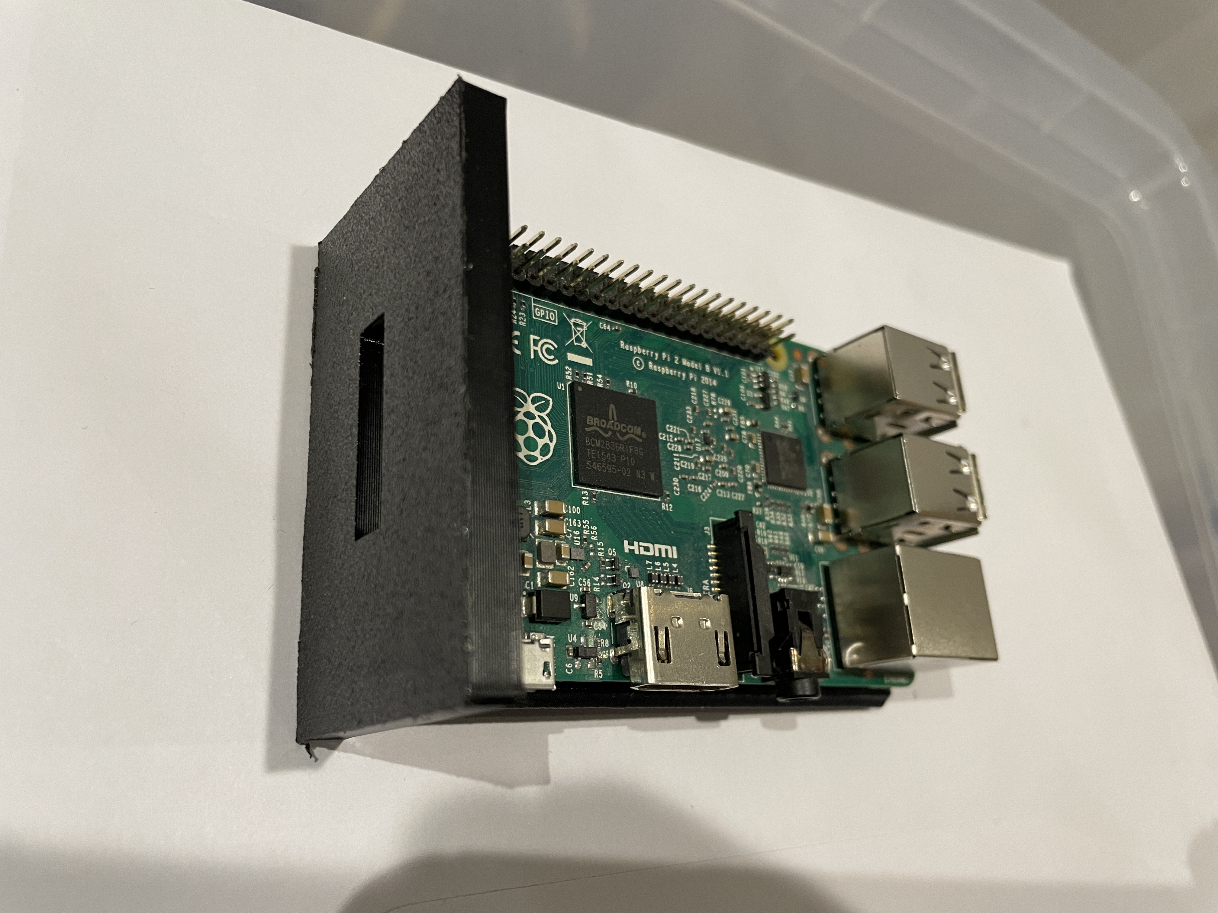
Changes to standard Raspberry Pi tray
Solid base added with recess to protect PCB from external damage. This extends to rear to allow for printing face down.
Increased space below front ports to make it easier to remove the ethernet cable.
Curved front replaced by a flat surround to hide the larger side indentations and frame.
Design changes to assist printing face down for a more consistent appearance, especially when using a textured printer bed.
Front now extends below the card improving appearance when printed face down and providing extra space for labels.
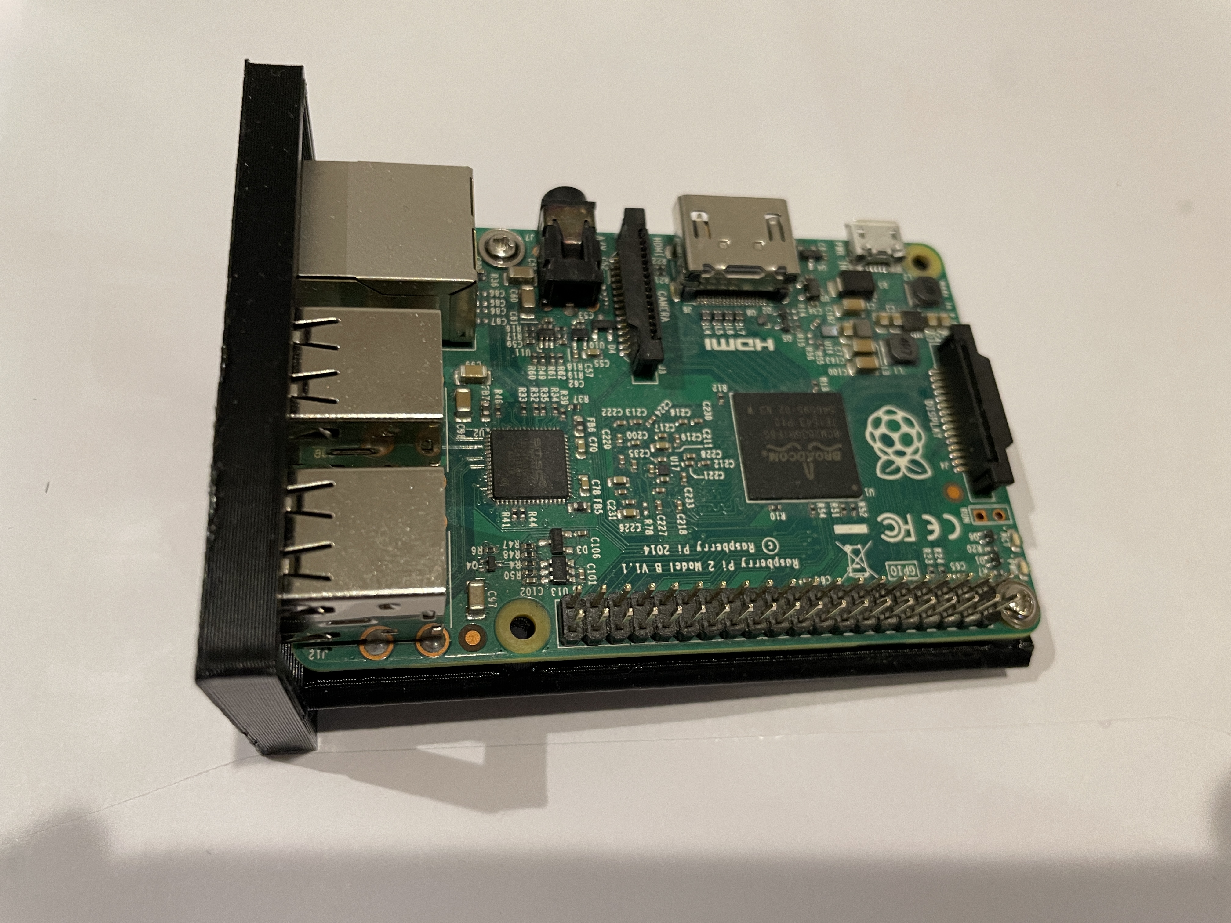
Note this tray has only been tested with a Pi 2. It should also fit a Pi 3 and 4 but I don't have one to test. Let me know if there are any issues.
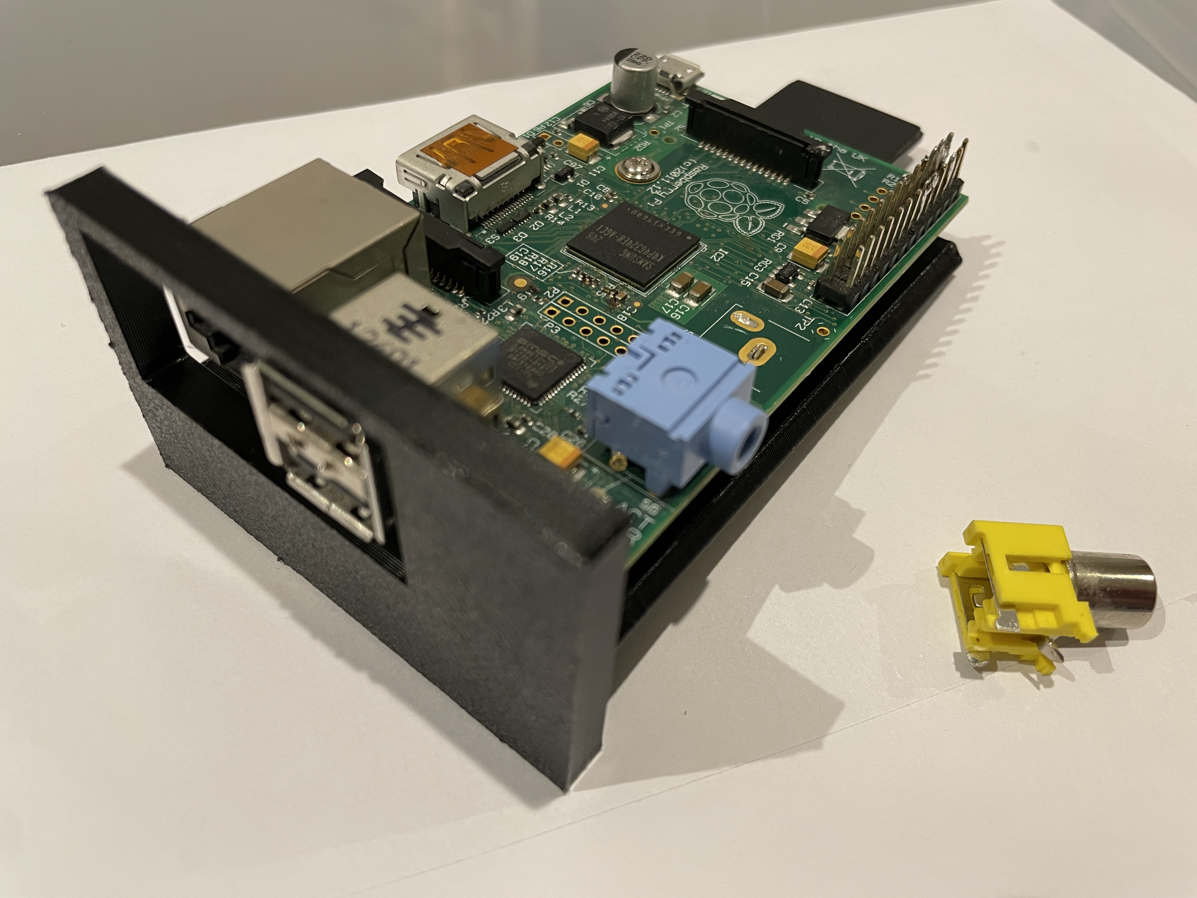
Reversed Raspberry Pi tray
This tray has the ethernet and USB connectors at the rear with the SD card visible through a slot in the front. This is useful when wiring needs to be routed to the rear of a rack and also provides space on the front panel which could be used for other items such as a small OLED display, connectors, buttons or switches.
This tray takes advantage of the new right hand slot for the headphone socket and the expanded rear opening for the ethernet and USB ports.
Tray for original Raspberry Pi Model B from 2012
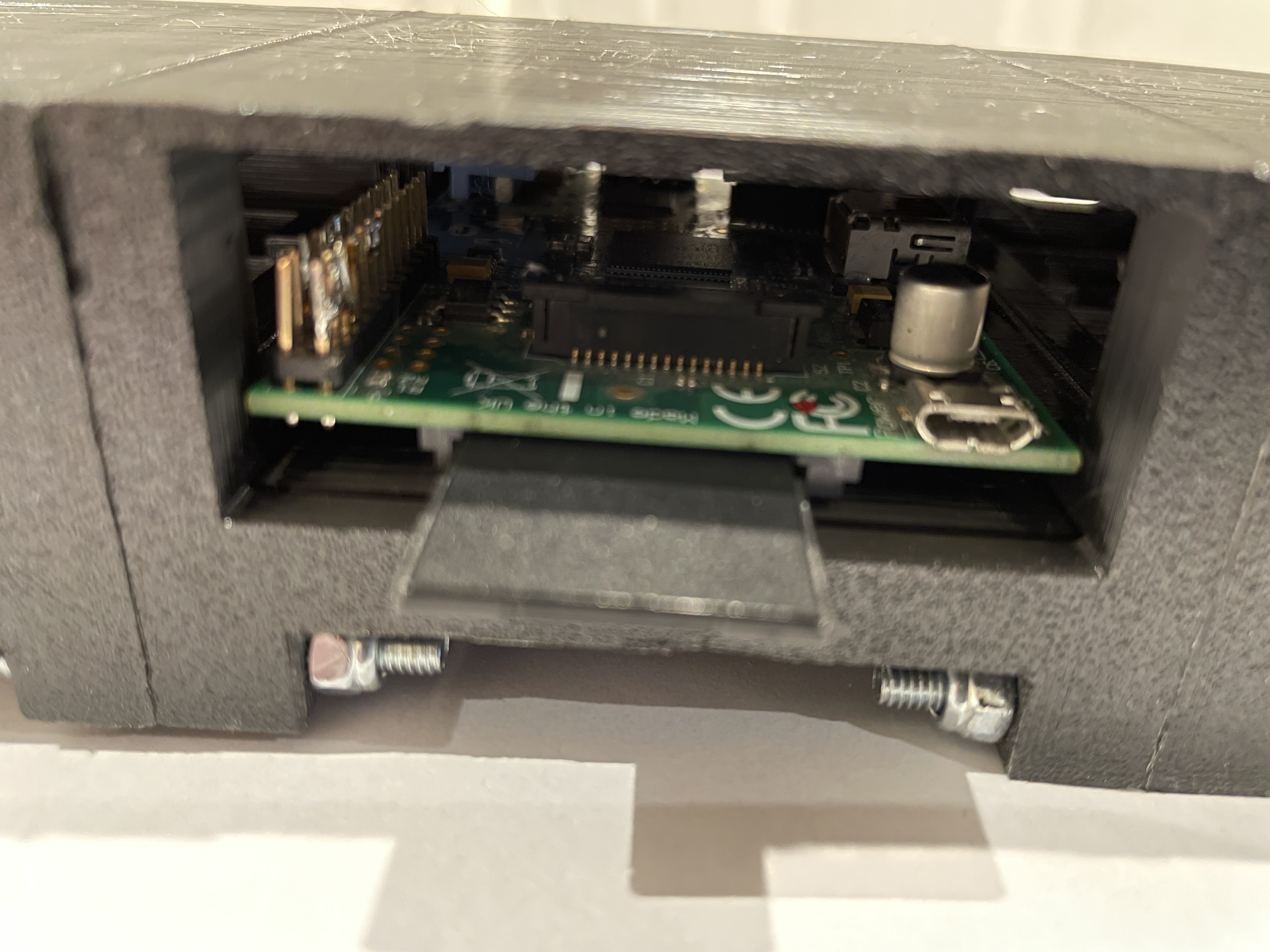
This tray has been designed for the original Raspberry Pi Model B from 2012 which has only two screw holes in unusual positions. As well as the two screw holes, two additional supports have been placed where they should not rest on any components. Due to this model's unusual support placement the base is solid with no recess to enable the slicer to efficiently fill the area.
On the first editions of the Raspberry Pi you will unfortunately need to remove the large yellow composite video phono socket, as otherwise it will be too wide to fit in the enclosure. The safest and easiest way I found to do this was by simply cutting its connections, though you'll need to be very careful not to damage anything else. No other ports need to be changed and the HDMI video output should be unaffected. Be aware there is a chance of damaging the Pi by doing this.
Since there are only two USB ports on the original Pi, an extra section has been added to the right hand side of the surround to cover the gap.
The tray takes advantage of the new right hand slot for the Pi's headphone socket, as this is on the right on this model.
Changes to edge bracket ears
The connecting screw holes have been changed to standard M4 size, as the original American size is hard to obtain in the UK.
The connecting screw holes have been lowered by 2mm and moved towards the rear by 1mm to allow the screw heads and nuts to fit.
Compatibility Notes
The frame should be compatible with trays from similar previous designs as long as any cards or "hats" are not too tall.
New trays that make use of the expanded sides in this design may not fit other similar frames.
The ears and main housing use a different connecting screw position and size, so can't be interchanged with previous designs.
This design has not been tested with a Pi PoE hat as I don't have one. If you can test this please let me know if it fits.
Additional parts required
14x M4x30mm screws to bolt parts together (could possibly be as long as 40mm). I used 1x Screwfix 3908J pack of 25 @ £2.79.
14x M4 nuts to bolt parts together. I used 1x Screwfix 64653 pack of 100 @ £4.29.
4x M2.5 x 12mm screws and nuts for each Raspberry Pi that needs to be mounted (or 2x for the 2012 Pi). Maximum 6 cards per 1U.
Printing and assembly
For the frame, rotate in your slicer so the rear is at base and ensure supports are enabled.
For the trays, rotate in your slicer so the front is at the base and ensure supports are enabled.
There will probably be multiple support bars printed for the sides and base of the frame but these should be easily to remove.
After printing a tray, ensure any support bars for the screw holes are removed or the Pi might not sit level.
Make sure to trim any overprinting from the sides of the frames to ensure they align correctly when assembled.
Don't over tighten the screws as that may distort the frames making trays harder to insert and remove.
Included files (includes stl, scad and Elegoo Neptune 4 Pro "draft" gcode for PETG)
readyformed-raspberry-pi-1u-frame Frame for all caddy types
readyformed-raspberry-pi-1u-ears Rack ears
readyformed-raspberry-pi-blank-panel Blanking panel for unused slots
readyformed-raspberry-pi-standard-tray Tray for Raspberry Pi with ethernet towards front of rack
readyformed-raspberry-pi-reverse-tray Tray for Raspberry Pi with ethernet towards rear of rack
readyformed-raspberry-pi-2012-tray Tray for 2012 Pi with ethernet towards front (requires video connector removal)
Print times for each file on an Elegoo Neptune 4 Pro using PETG without high speed fans
Frame 2h 07m 26s 6 x prints required for complete unit
Bracket ears (pair) 56m 20s 1 x print required as single print has both ends.
Standard tray for Raspberry Pi 1h 16m 07s Print as required.
Standard tray for Raspberry Pi 2012 1h 14m 12s Print as required.
Blanking panel 28m 11s Print as required.
Printer used: Elegoo Neptune 4 Pro
Material: PETG
Licence:
This design is licensed under Creative Commons - Attribution: Readyformed Solutions
Based on the excellent design by russross, licensed under Creative Commons - Attribution
Page created: 09/12/2023.
DOWNLOAD FILES AS ZIP
This is a remix of an existing excellent 1U design by russross with changes to allow assembly using more commonly available M4 screws, elements added to more easily allow new types of tray to be created for alternative devices and for a Pi to be mounted in the opposite direction. In addition to technical and cosmetic changes, a top cover has been added to the frame and a lower cover to the trays to protect devices from other equipment.
In this design the front panel of each tray has a flat surface and forms the majority of the visible area. By printing the trays face down on the printer, this creates a very clean visual appearance which can be improved further by using a textured bed.
These frames are sometimes referred to as "hot swapable" but they're better described as "interchangeable". While you can easily remove a device without affecting the others, in some cases you may want to create an "appliance" of multiple devices, possibly with internal wiring. In that instance having panels that fit flush with the slot also becomes an additional consideration.
Trays are included for later Raspberry Pi models in both forward and reverse orientation, as well blanking panels and a tray for the original Pi from 2012.
Changes to the holder frame
Instead of threaded rods, gaps have been added so screws and nuts can be used instead as these are often more easily available.
The connecting holes have been changed to accommodate standard M4 screws, as the original American size is hard to obtain in the UK.
The connecting holes have been lowered by 2mm and moved by 1mm towards the rear to allow the screw heads and nuts to fit.
The rear opening is now larger to make it easier to design modules for other devices or for a tray with the Pi reversed.
The slot for the Pi headphone socket has been made taller and deeper to allow other boards with different side ports to be used.
This slot is now also replicated on the right to allow a tray for a Pi mounted in reverse or alternative boards to be used.
The front angle at the base has been removed and a cover added to hide the area where the screws are now located.
A cover has been added over the top to help prevent adjacent equipment or cables causing damage or short circuits.
Readyformed text added to allow easy identification of the wider slot type. This text is hidden when a tray or blank is inserted.
Changes to standard Raspberry Pi tray
Solid base added with recess to protect PCB from external damage. This extends to rear to allow for printing face down.
Increased space below front ports to make it easier to remove the ethernet cable.
Curved front replaced by a flat surround to hide the larger side indentations and frame.
Design changes to assist printing face down for a more consistent appearance, especially when using a textured printer bed.
Front now extends below the card improving appearance when printed face down and providing extra space for labels.
Note this tray has only been tested with a Pi 2. It should also fit a Pi 3 and 4 but I don't have one to test. Let me know if there are any issues.
Reversed Raspberry Pi tray
This tray has the ethernet and USB connectors at the rear with the SD card visible through a slot in the front. This is useful when wiring needs to be routed to the rear of a rack and also provides space on the front panel which could be used for other items such as a small OLED display, connectors, buttons or switches.
This tray takes advantage of the new right hand slot for the headphone socket and the expanded rear opening for the ethernet and USB ports.
Tray for original Raspberry Pi Model B from 2012
This tray has been designed for the original Raspberry Pi Model B from 2012 which has only two screw holes in unusual positions. As well as the two screw holes, two additional supports have been placed where they should not rest on any components. Due to this model's unusual support placement the base is solid with no recess to enable the slicer to efficiently fill the area.
On the first editions of the Raspberry Pi you will unfortunately need to remove the large yellow composite video phono socket, as otherwise it will be too wide to fit in the enclosure. The safest and easiest way I found to do this was by simply cutting its connections, though you'll need to be very careful not to damage anything else. No other ports need to be changed and the HDMI video output should be unaffected. Be aware there is a chance of damaging the Pi by doing this.
Since there are only two USB ports on the original Pi, an extra section has been added to the right hand side of the surround to cover the gap.
The tray takes advantage of the new right hand slot for the Pi's headphone socket, as this is on the right on this model.
Changes to edge bracket ears
The connecting screw holes have been changed to standard M4 size, as the original American size is hard to obtain in the UK.
The connecting screw holes have been lowered by 2mm and moved towards the rear by 1mm to allow the screw heads and nuts to fit.
Compatibility Notes
The frame should be compatible with trays from similar previous designs as long as any cards or "hats" are not too tall.
New trays that make use of the expanded sides in this design may not fit other similar frames.
The ears and main housing use a different connecting screw position and size, so can't be interchanged with previous designs.
This design has not been tested with a Pi PoE hat as I don't have one. If you can test this please let me know if it fits.
Additional parts required
14x M4x30mm screws to bolt parts together (could possibly be as long as 40mm). I used 1x Screwfix 3908J pack of 25 @ £2.79.
14x M4 nuts to bolt parts together. I used 1x Screwfix 64653 pack of 100 @ £4.29.
4x M2.5 x 12mm screws and nuts for each Raspberry Pi that needs to be mounted (or 2x for the 2012 Pi). Maximum 6 cards per 1U.
Printing and assembly
For the frame, rotate in your slicer so the rear is at base and ensure supports are enabled.
For the trays, rotate in your slicer so the front is at the base and ensure supports are enabled.
There will probably be multiple support bars printed for the sides and base of the frame but these should be easily to remove.
After printing a tray, ensure any support bars for the screw holes are removed or the Pi might not sit level.
Make sure to trim any overprinting from the sides of the frames to ensure they align correctly when assembled.
Don't over tighten the screws as that may distort the frames making trays harder to insert and remove.
Included files (includes stl, scad and Elegoo Neptune 4 Pro "draft" gcode for PETG)
readyformed-raspberry-pi-1u-frame Frame for all caddy types
readyformed-raspberry-pi-1u-ears Rack ears
readyformed-raspberry-pi-blank-panel Blanking panel for unused slots
readyformed-raspberry-pi-standard-tray Tray for Raspberry Pi with ethernet towards front of rack
readyformed-raspberry-pi-reverse-tray Tray for Raspberry Pi with ethernet towards rear of rack
readyformed-raspberry-pi-2012-tray Tray for 2012 Pi with ethernet towards front (requires video connector removal)
Print times for each file on an Elegoo Neptune 4 Pro using PETG without high speed fans
Frame 2h 07m 26s 6 x prints required for complete unit
Bracket ears (pair) 56m 20s 1 x print required as single print has both ends.
Standard tray for Raspberry Pi 1h 16m 07s Print as required.
Standard tray for Raspberry Pi 2012 1h 14m 12s Print as required.
Blanking panel 28m 11s Print as required.
Printer used: Elegoo Neptune 4 Pro
Material: PETG
Licence:
This design is licensed under Creative Commons - Attribution: Readyformed Solutions
Based on the excellent design by russross, licensed under Creative Commons - Attribution